- Published on
- Published on
- (Last revised
I installed LED lighting on my 3D printer
- Authors

- Name
- Muhammad Fareez Iqmal
- @iqfareez
Having to turn on the main room light can be too much, especially at night. It might disturb other people who live in the same room with me too. From that, I got the idea of installing some lighting for my 3D printer.
I'm using an Artillery Hornet FDM 3D printer. It is my first 3D machine and I love it.
The idea
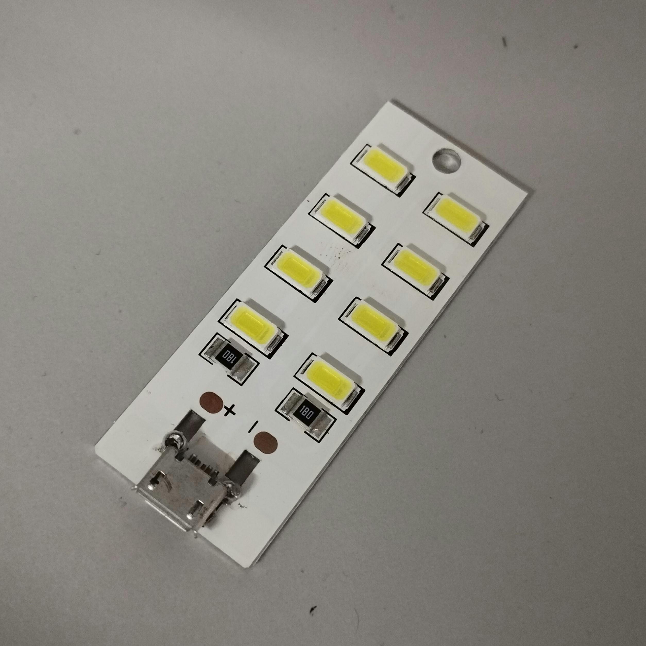
Initially, I thought to just solder some LEDs that I had lying around on a donut board. But, the light intensity of those LEDs is not so bright. I also need to calculate the required amount of resistance and place them on the board. Requires some work. One day, I scrolled through Shopee and found this cheap SMD LED board. I think it may fit perfectly with this project. It also comes with the micro USB port, enabling easy testing and prototyping.
Designing the LED holder
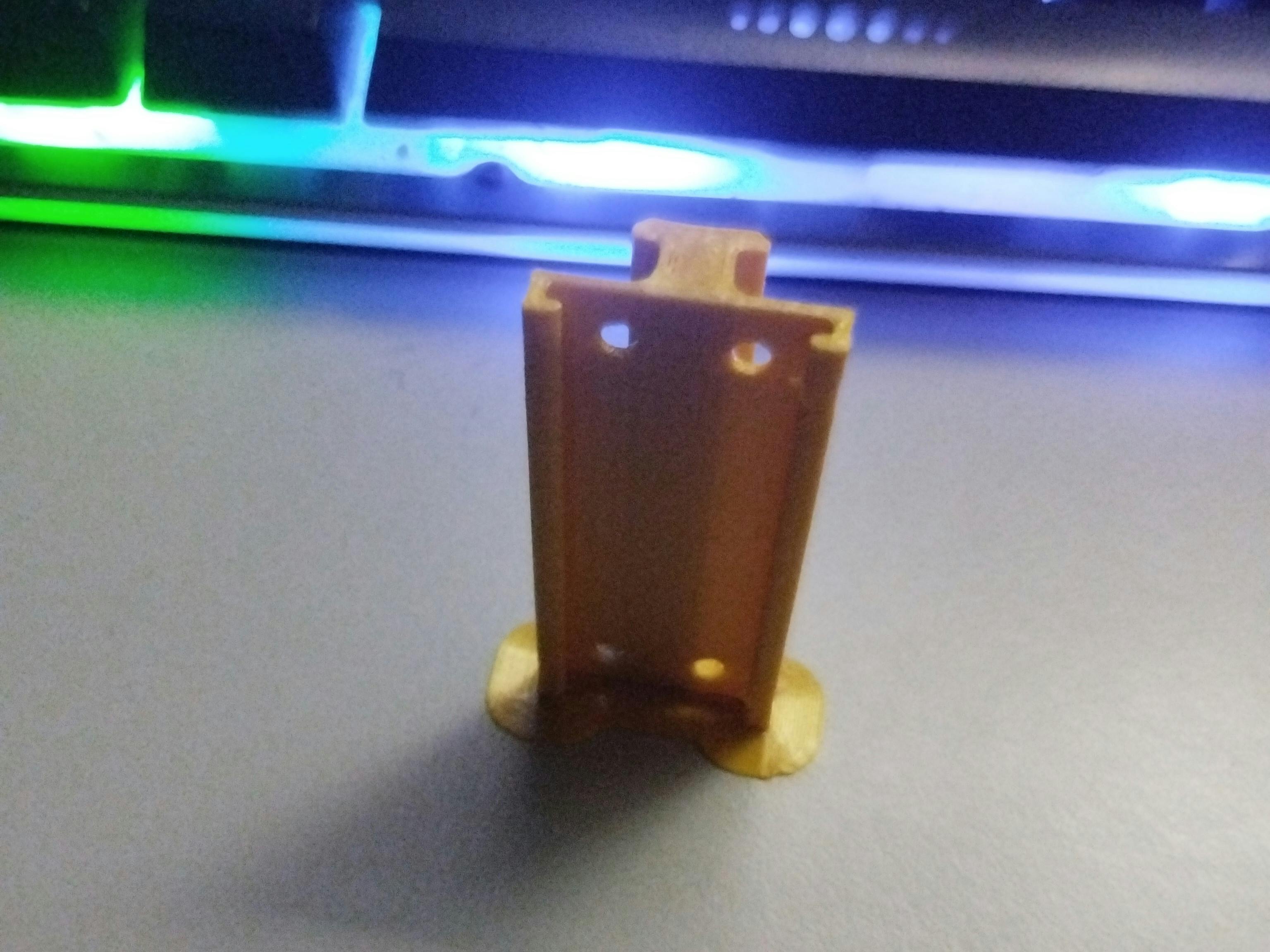
When the LED was delivered, I tested it and measured its dimensions to design a holder for it. This holder will be fitted into the aluminum profile of the printer. Using Fusion 360 to make the design, and after a few iterations, I came up with this:
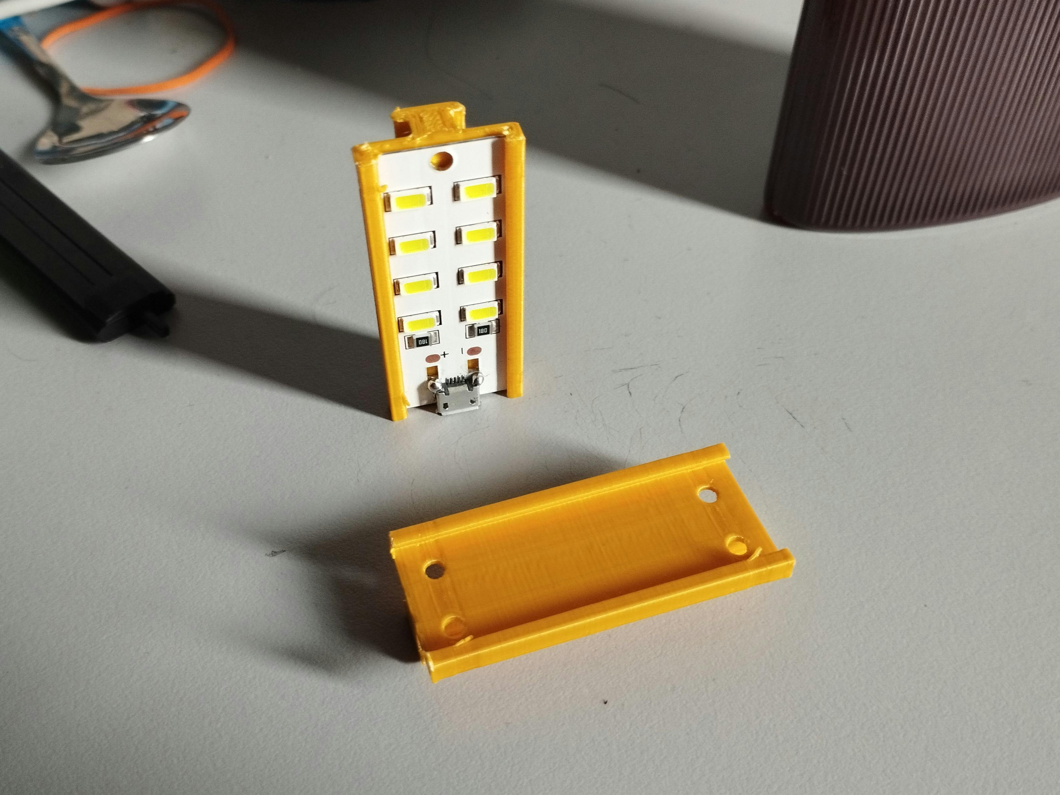
Sent it to my printer to print. This is the result, very satisfying.
You can print/modify the holder yourself. Please find the files here.
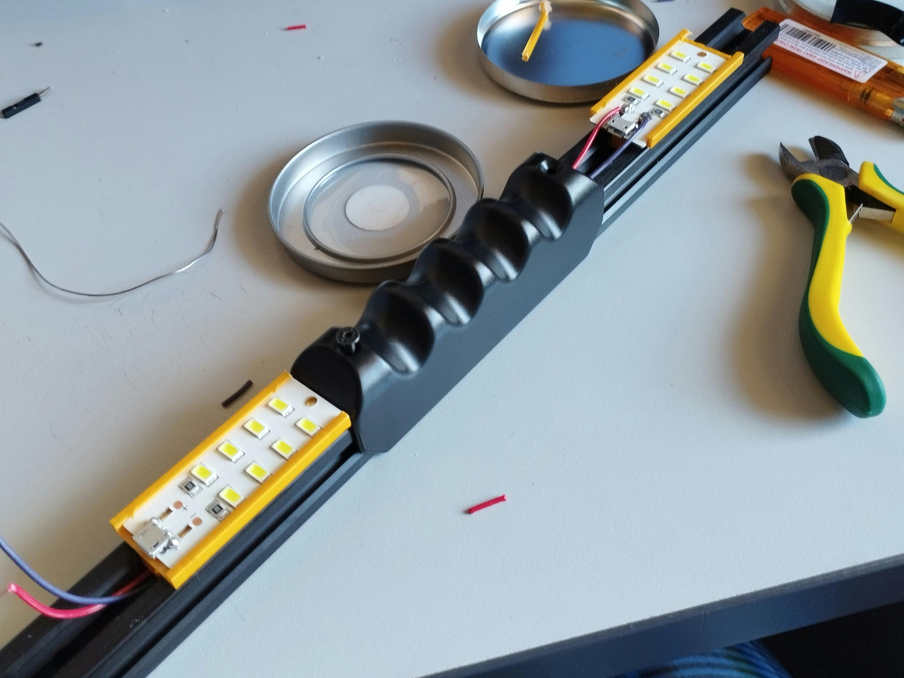
Then, slide the LED board into its casing
Power supply
At the beginning, I was planning to use the printer's power supply module, so that the light will automatically turn on when I turn on the printer. To access the module, it has no other way than to access it from the bottom. I've tried to pry it open, but in the middle of the process, I feel it is too difficult and not worth it.
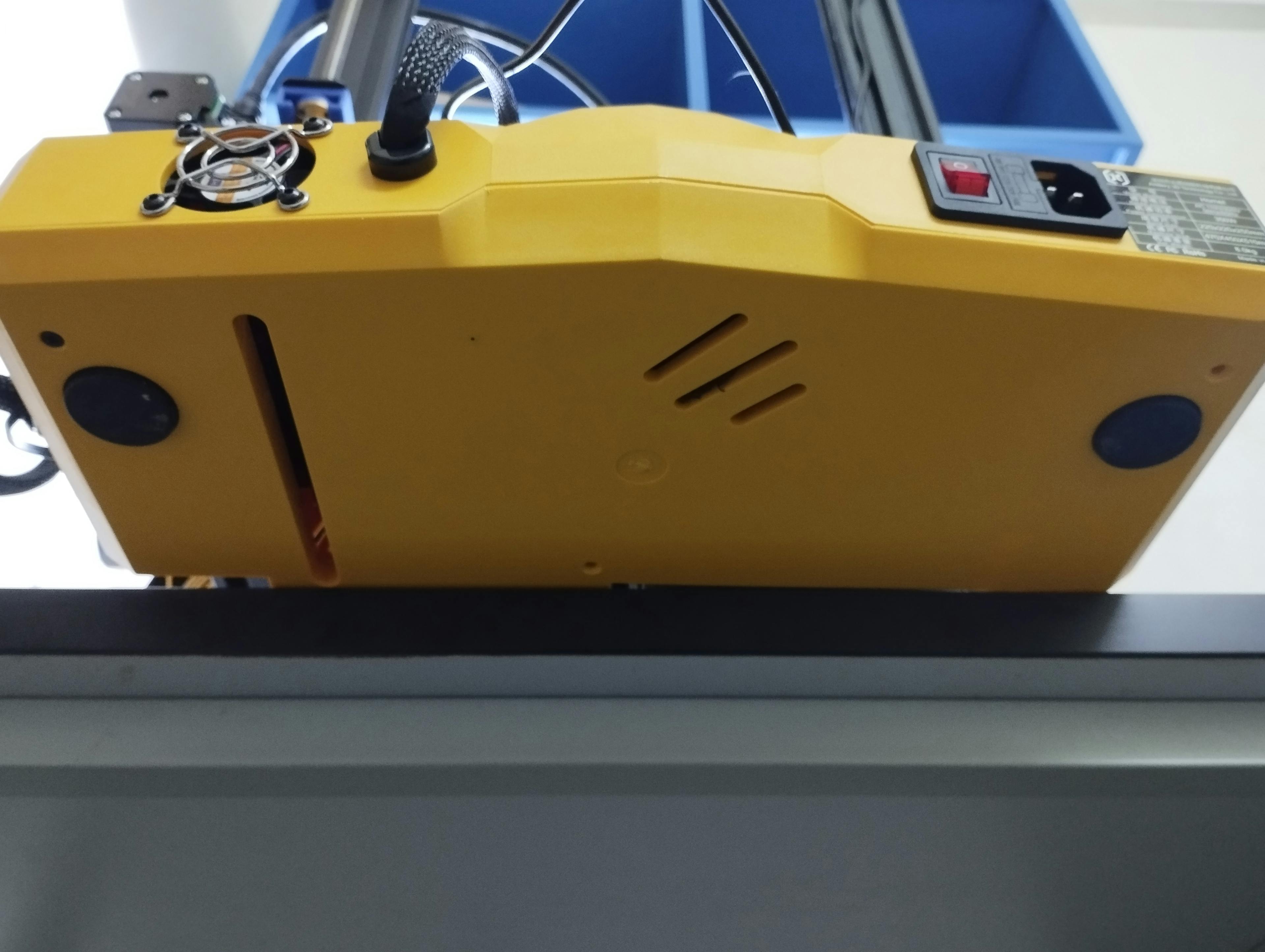
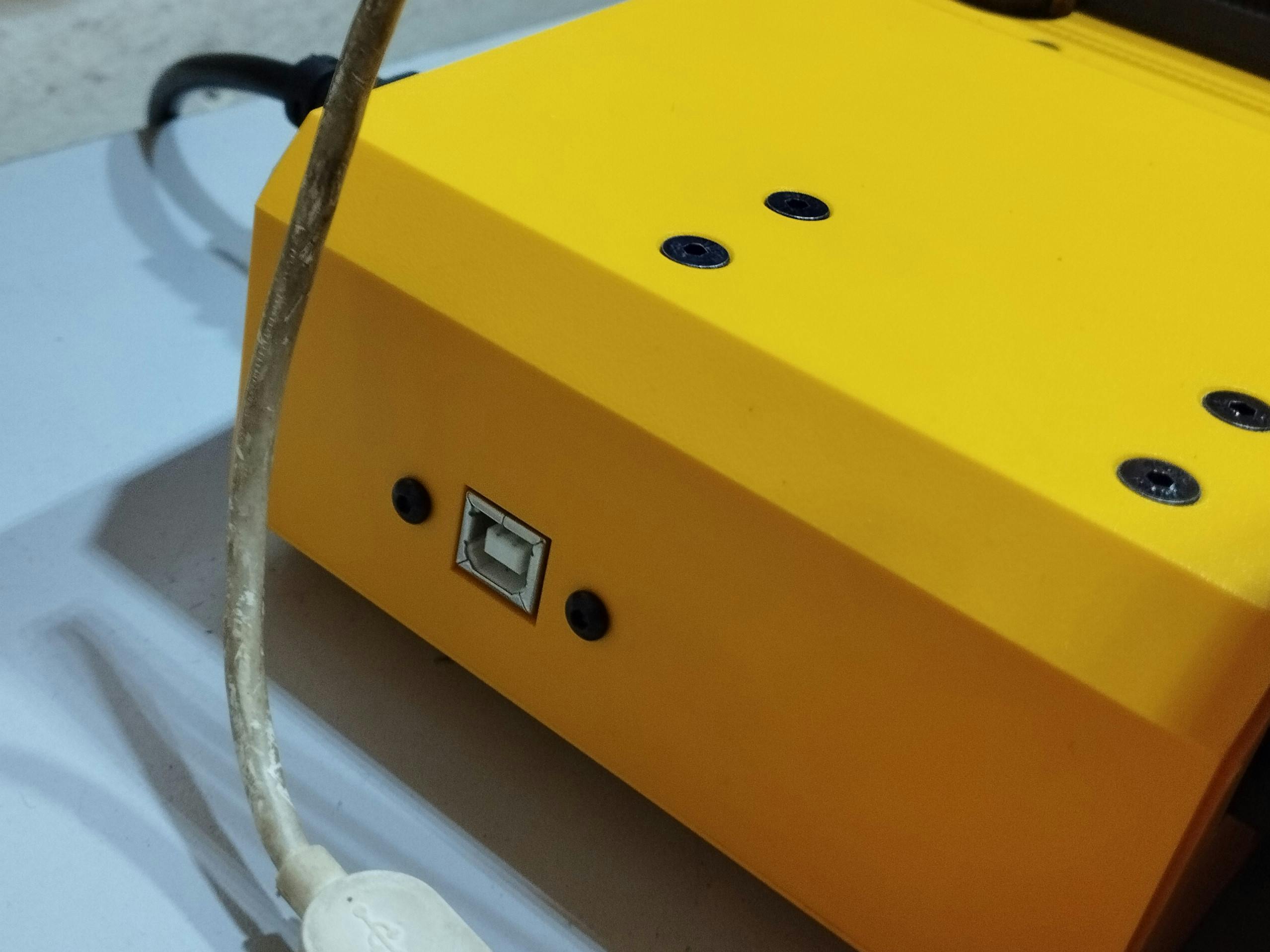
There is a USB type B port on the side of the printer for data transmission purposes, so I'm not so sure if I can get enough current from the port, plus I did not have the USB-B cable.
In the end, I've decided to just use one power bank I have lying around. The wiring should be straightforward; USB to LED.
Update 2024: Attempting to pull power from an unused port from the printer. Spoiler: It didn't work There was an unused Z-Probe connector on the side of the printer. I think if I can get the power from there, it would make the setup cleaner and eliminate the need for the power bank.
So I shopped for the JST XH2.54 XH connector and USB female and made the wiring. But after connecting to the LEDs, the light was very dim (which indicates there might not be enough current provided by the port). Seems like we just stick to the power bank.
Wiring
First, I took off the top gantry of the printer. It is held by 4 screws and can be removed using the Allen key. Luckily, it isn't attached to any stepper motor etc. It is just there by itself, so removing it is a piece of cake. The holder also needs to be removed.
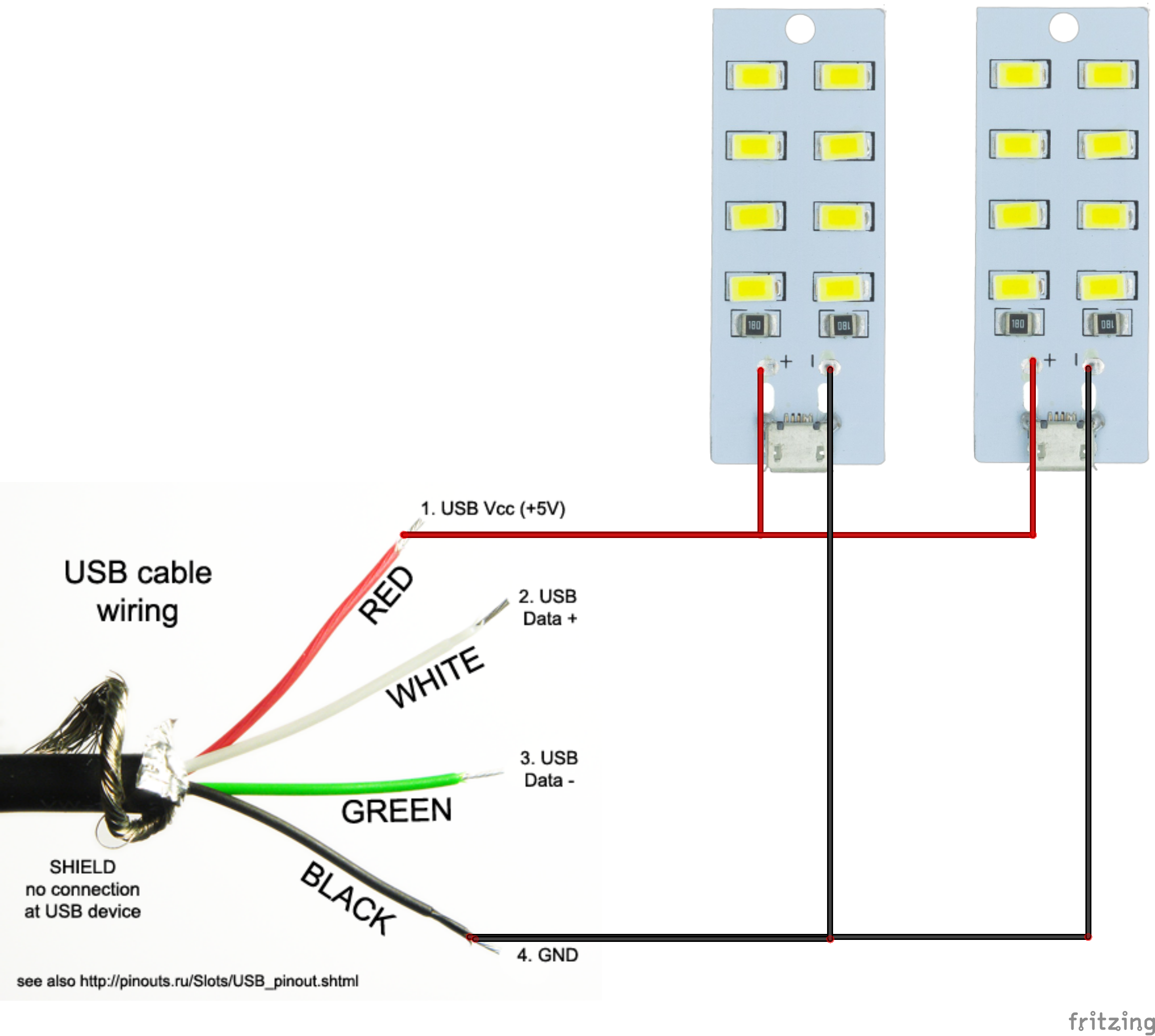
Both LED boards will connect with a parallel configuration. The LED board has 2 pads with positive and negative, so the wires can be soldered into it. Strip some jumper wires, expose the copper wire as needed only, not too long. Solder the wires to the LED board.
In case it is still unclear, the diagram below should be helpful. (Note: You can replace the USB with other 5V sources. Eg: Arduino 5V output)
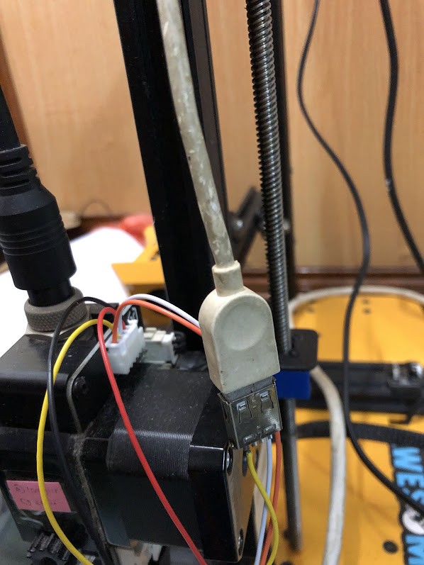
Find some USB connector you had, perhaps from an old phone charger etc. Strip the wires. For data cable USB2.0, usually, there will be 4 wires. We only need the power so find a wire with red (positive supply) and black (ground). Because the wire is short in my case, I connected it with another wire that is soldered to the LED board. But if your cable is long enough, you can just solder it directly to the LED board.
warning
Do not solder the wire when the LED board is attached to its plastic case, the case may deform under high temperature.
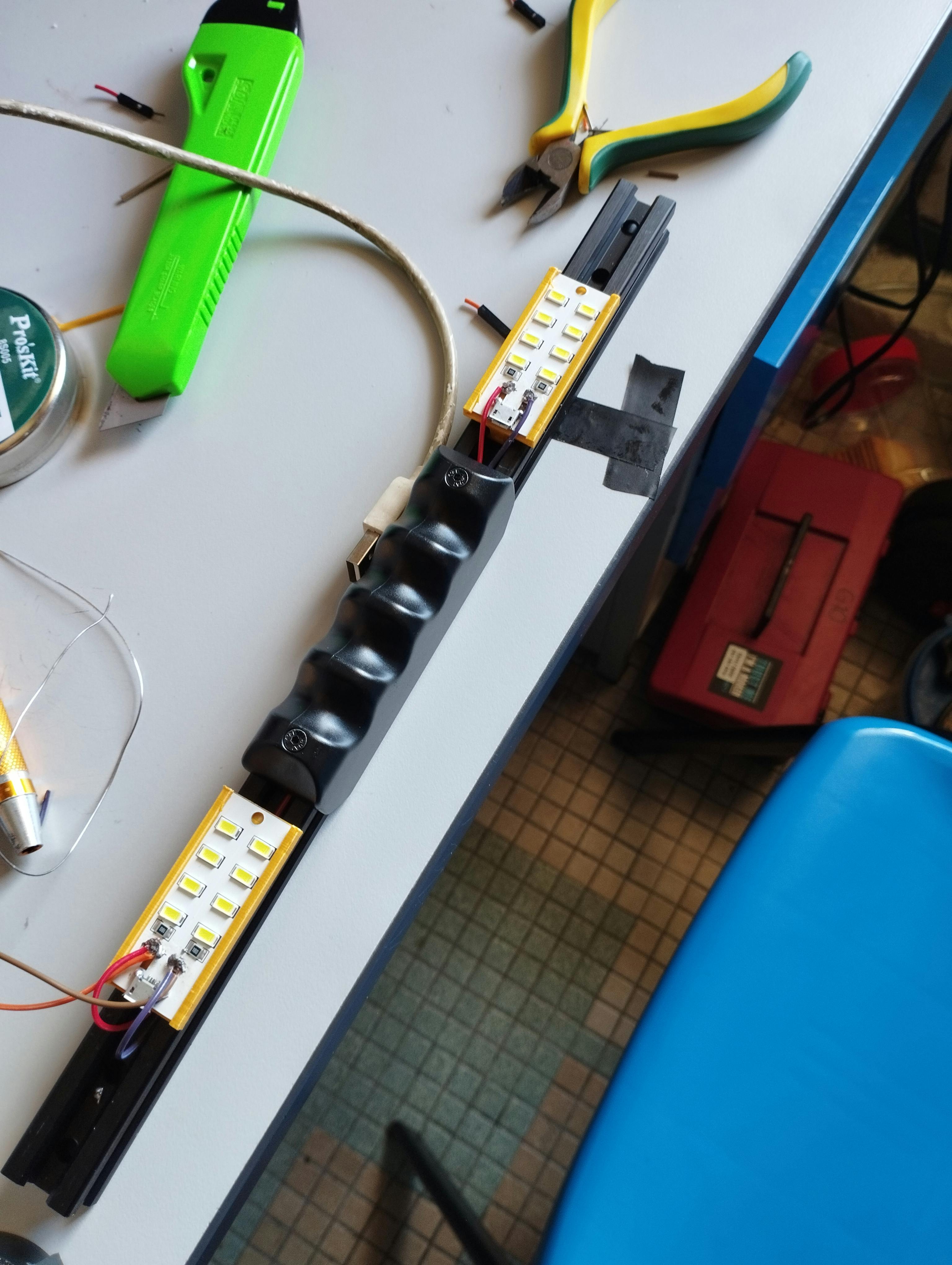
The picture below is the combined wire. I use heat shrink to cover the wire to prevent a short circuit (precaution).
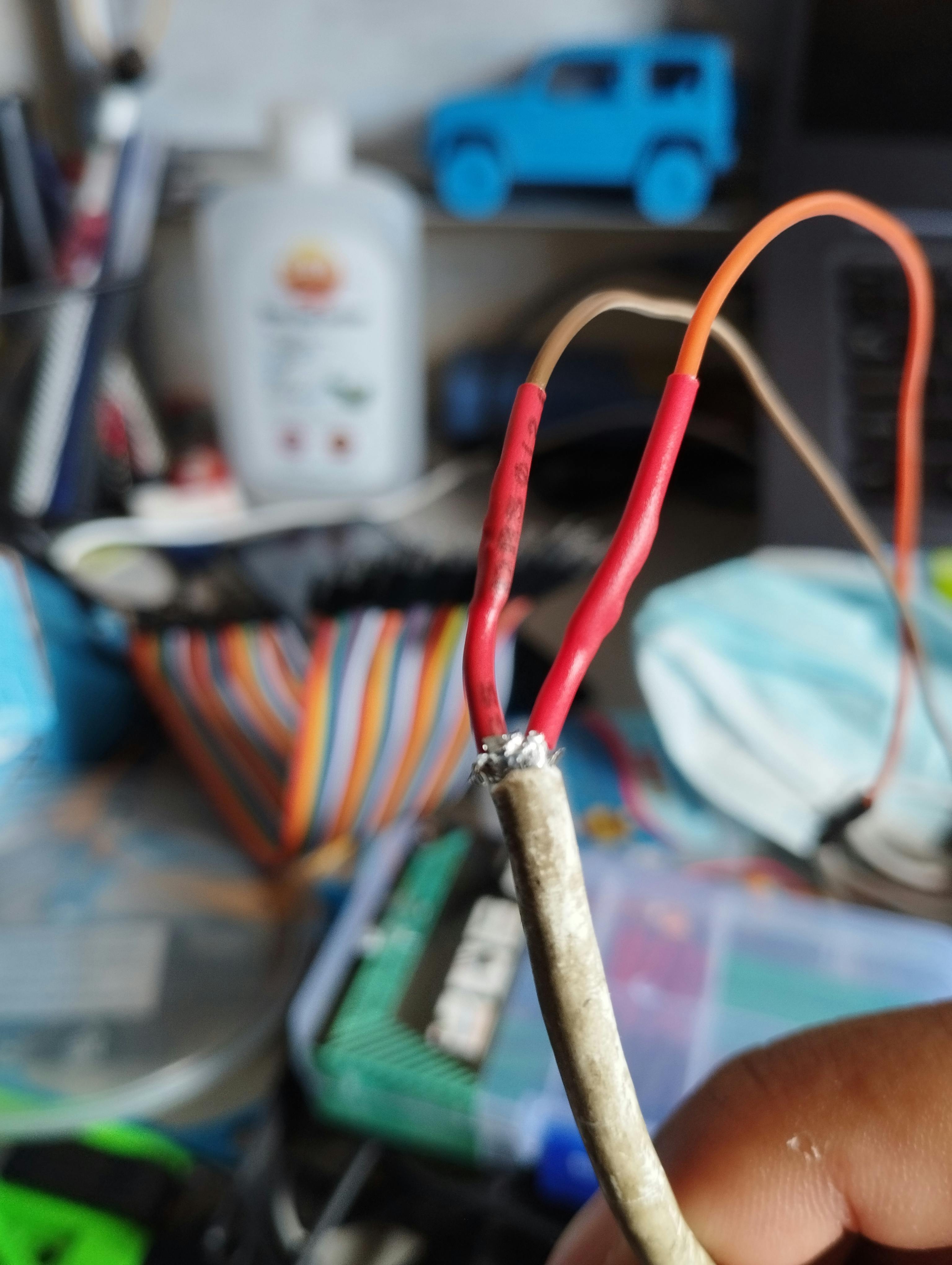
Now, route the wire neatly inside the aluminum profile. Then, screw the handle in place, be careful not to screw the wires underneath. Connect the USB to power to see if the light turns on. After that, we can proceed to remount the gantry back to the printer.
After some soldering
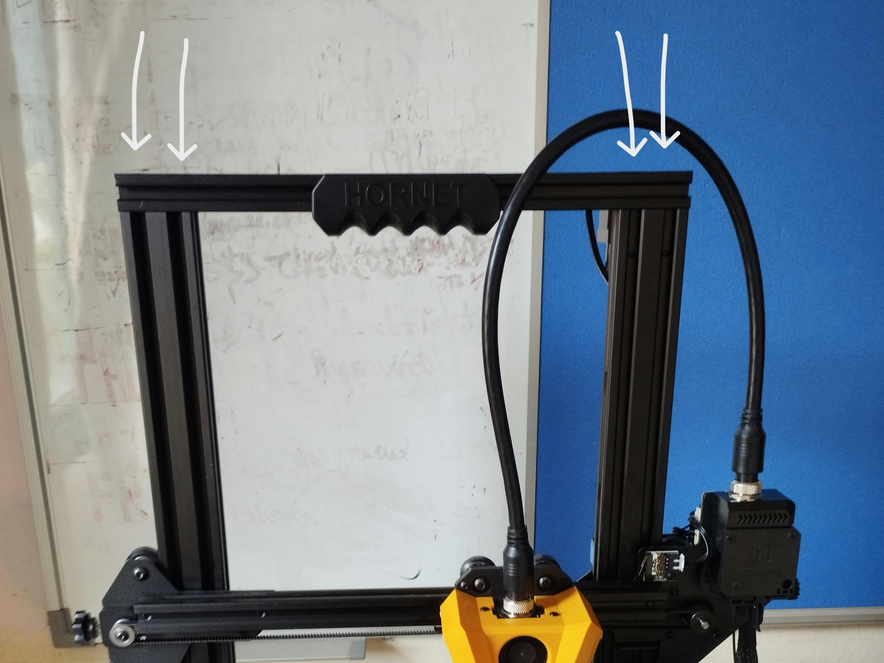
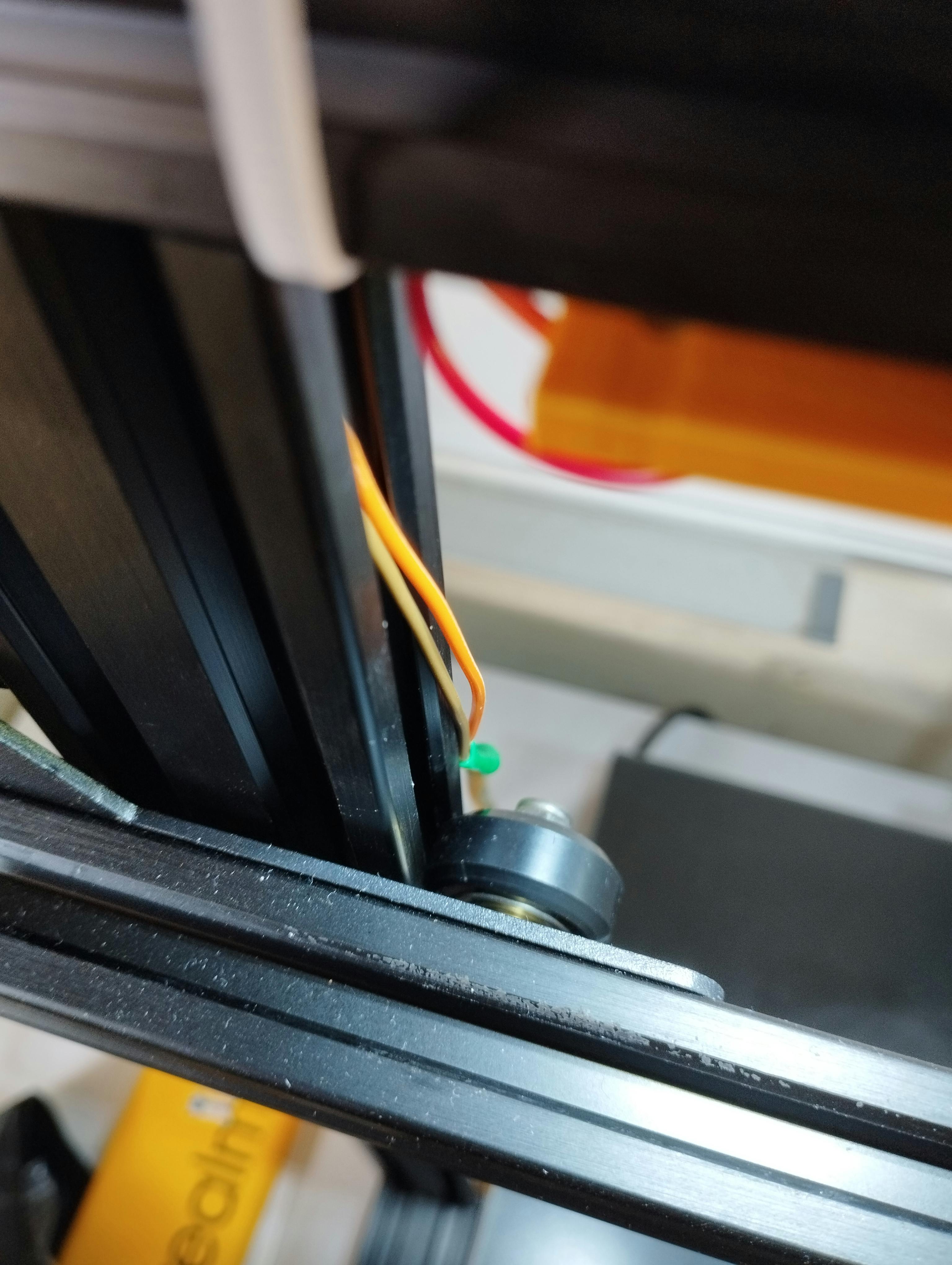
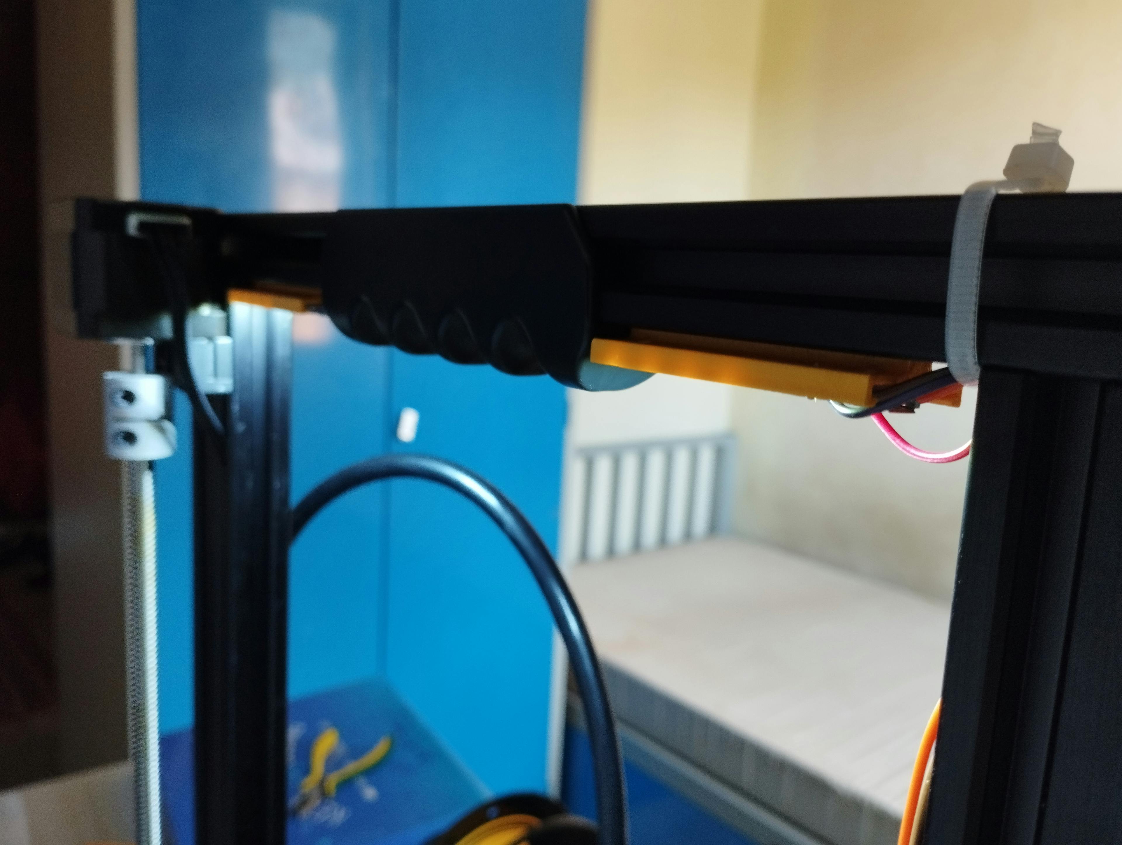
Route the USB cable at the back of the vertical gantry. Be sure not to disturb the movement of the z-axis gantry movements. Optionally, use some cable ties to reduce the tension of the wires and to keep it clean.
The picture below is the z-axis at its maximum (250mm), there are some safe spaces to route the wires.
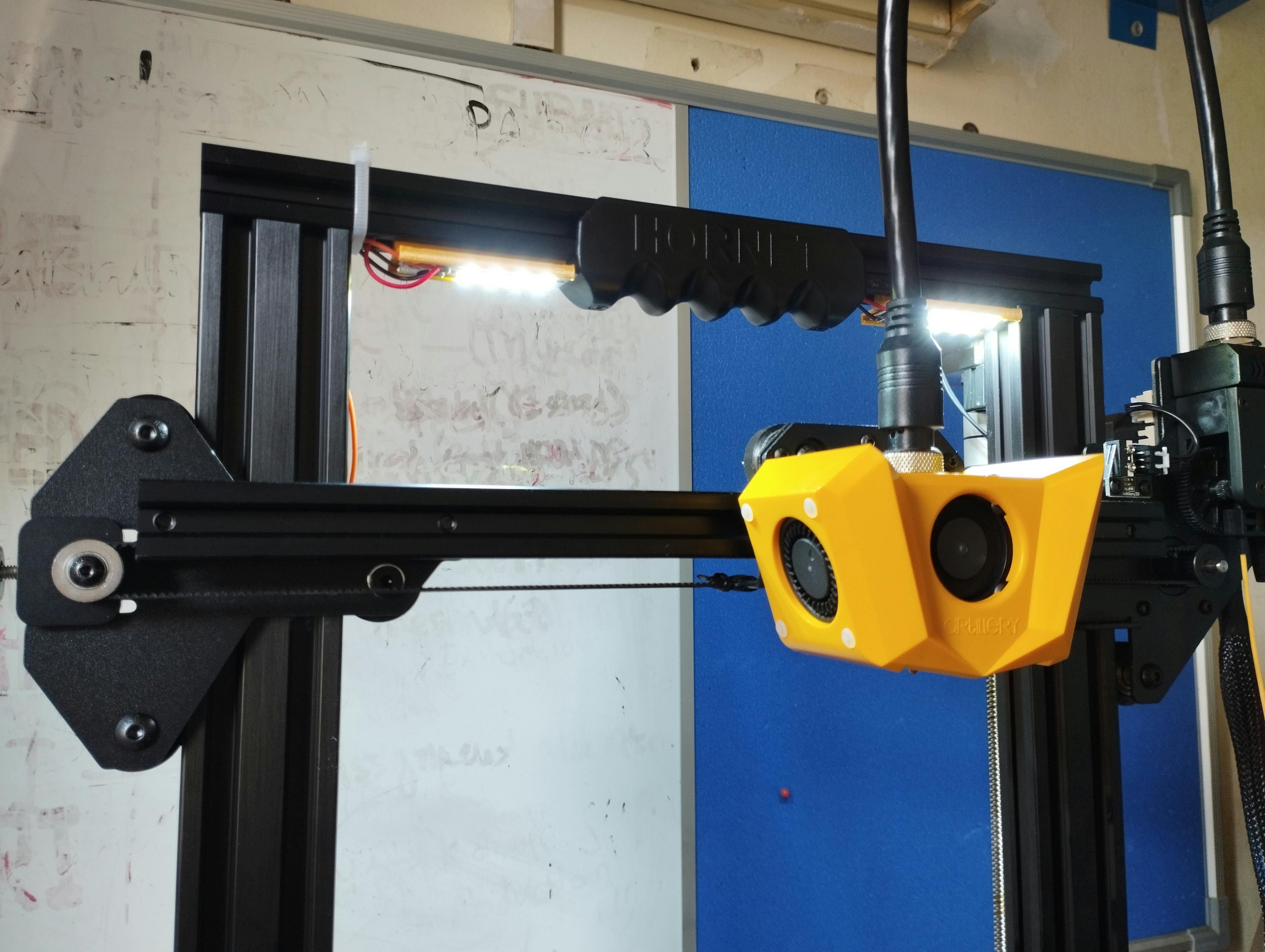
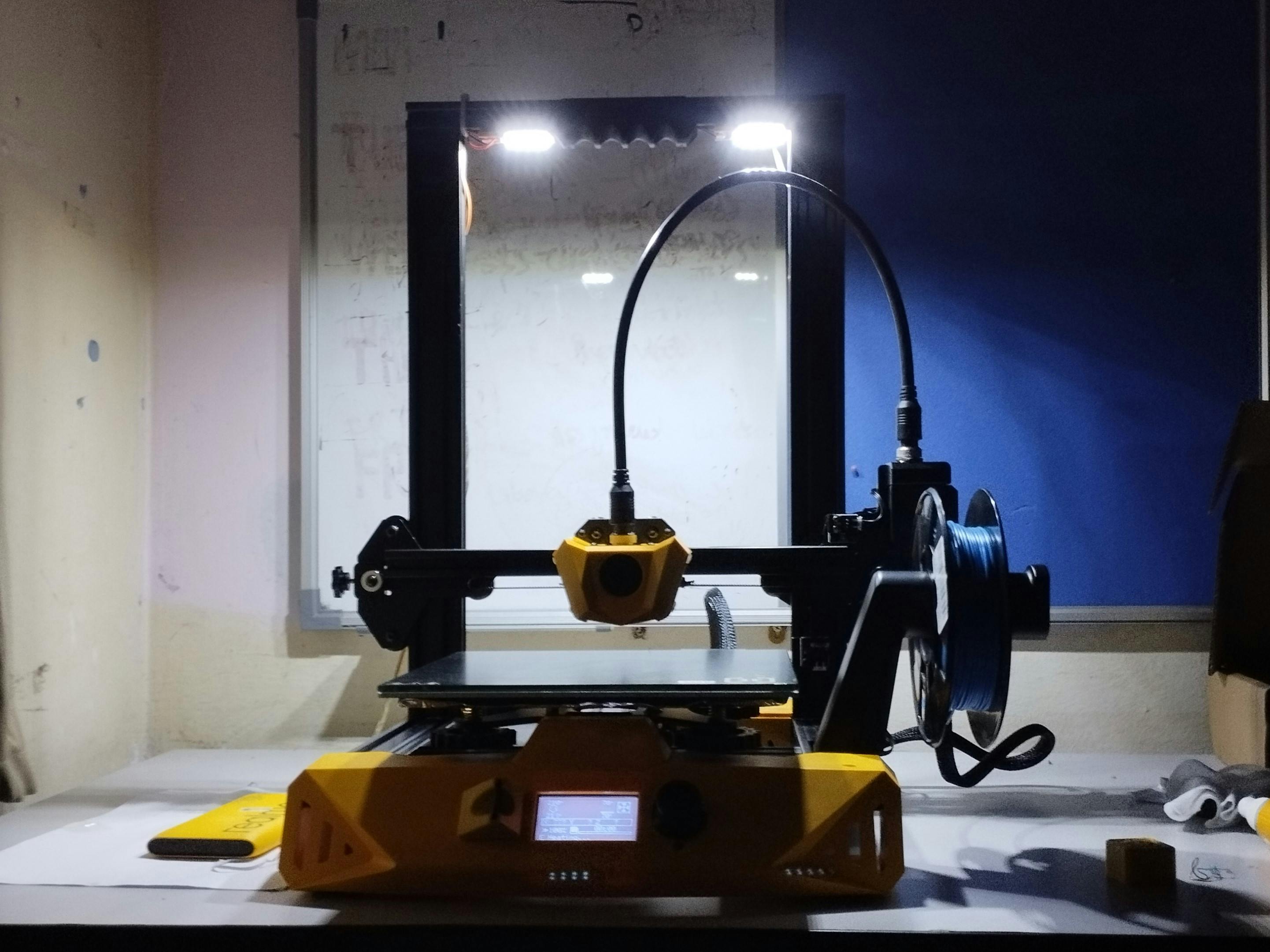
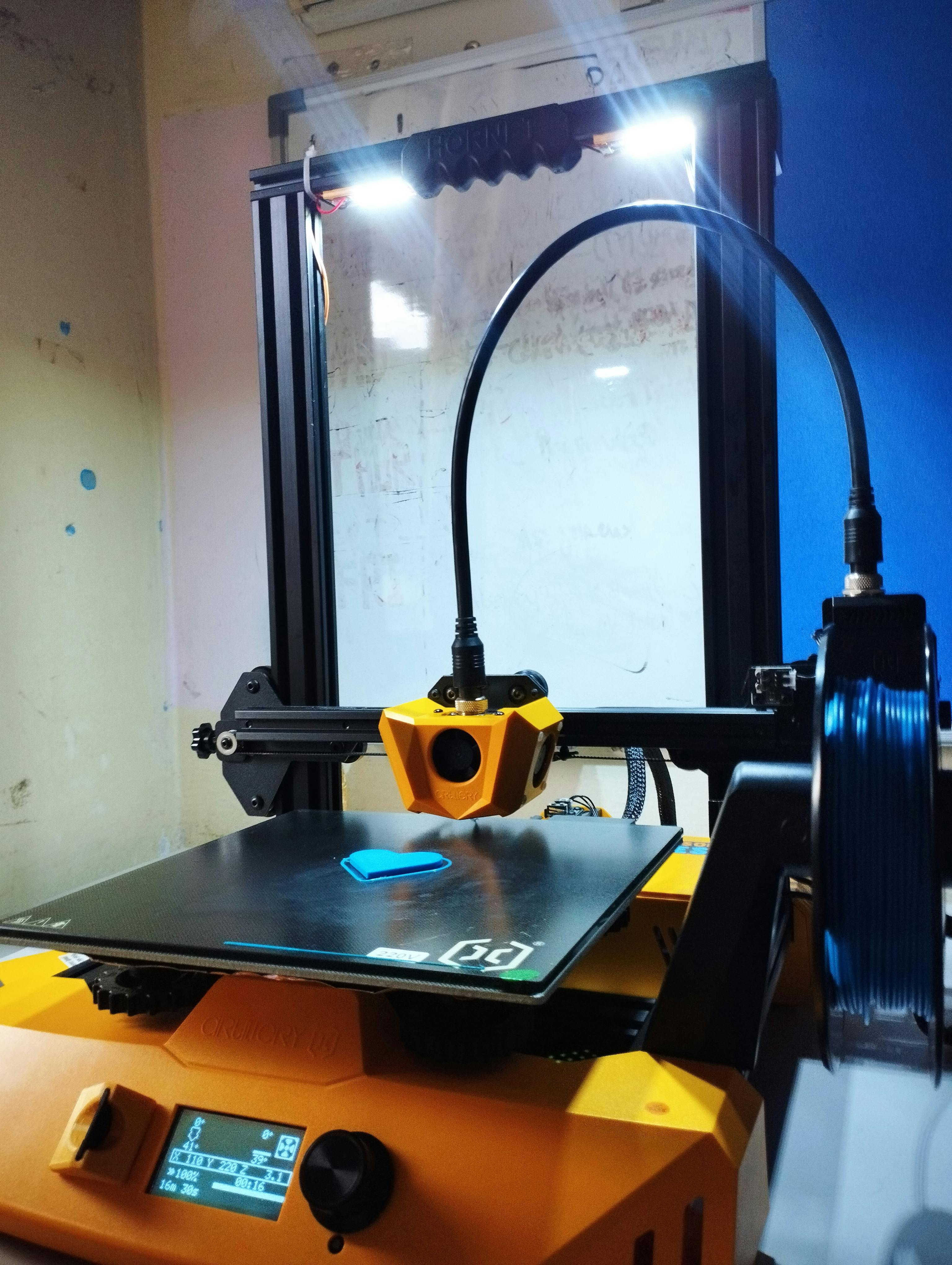
Final results
You can also watch my cringe YouTube shorts here.
Further improvements
For now, the problem is I need to manually turn on/off the light. What I want is for the light to automatically turn itself off when the printer is finished printing.
I have a few ideas running in my mind right now:
Access Marlin to get printing status
Marlin is the firmware that runs on the 3D printer. It is open source and (I think) can be accessed via a USB port, just like an Arduino. I mean I've done car interfacing before, so to interface with the printer it shouldn't be that hard, or is it?
Well, for now, I couldn't find anything online, so I have to dig down by myself to see whether it is possible or not.
Timer off light
This one is straightforward. Just hook up some microcontroller, add buttons to adjust the countdown timer, relay etc. The timer can be set based on the slicer's estimated printing time.
Concluding remarks
Anyway, thanks for reading. I hope you find this project interesting. Put your comments below if you have any. I'm just going to finish up the article(s) that have been in my drafts for eternity now.