- Published on
- Published on
- (Last revised
Count 0-9 using Arduino Uno (ATMega328P) in Assembly
- Authors

- Name
- Muhammad Fareez Iqmal
- @iqfareez
The lab task assigned to us was to count from 00-99 using a 7 Segment Display, the program must be written in Assembly. Fortunately, the 7 segment decoder was not enough for everyone in the lab, so the tasks are simplified to count from 0-9 only, and repeats.
As someone who is familiar with high-level programming languages like Java, Python, etc., coding in assembly is infuriating 😂. The sweet side is that Assembly allows us to 'talk' directly to the bare metal, removing the unnecessary abstraction, solving performance issues, coding like a chad, and understanding how the hardware works.
In this article, we're going to dive into how the programs work on ATMega328P.
What you'll need
Hardware
- Arduino Uno (ATMega328P)
- 7-Segment Display
- BCD to 7-Segment Decoder. Eg: HD74LS47 (for common anode) or HD74LS48 (for common cathode)
- Breadboard & some jumper wires
Software
- Microchip Studio (aka Atmel Studio 7)
- XLoader (to upload the program to Arduino)
Manual (Must have for reference)
Understanding the ports
Arduino Uno pinout diagram (credit Arnab Kumar Das)
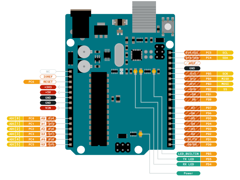
The ATMega328P has several I/O pins, which can be used as input or output. The pins are grouped into ports, which are labeled as PORTB, PORTC and PORTD. As you might notice in the image above, the lower left side is PD0 to PD7, then continued with PB0 to PB5 and so on.
Binary Coded Decimal (BCD)
Binary-coded decimal is a system of writing numerals that assigns a four-digit binary code to each digit 0 through 9 in a decimal (base 10) number. Note that BCD is not the same as binary representation. (Read more here) Both ICs I've mentioned above accept 4-bit BCD input, and outputs to 7-segment display.
Below is the truth table for the decoder. Note that in this article, I'm using the DCBA convention instead of ABCD. (Image credit: Digital Electronics)

Now, for example, we want to display a digit 4 on the 7-Segment display, how do we do that?
That's right. We send the 0100 to the decoder. Let's construct our circuit first.
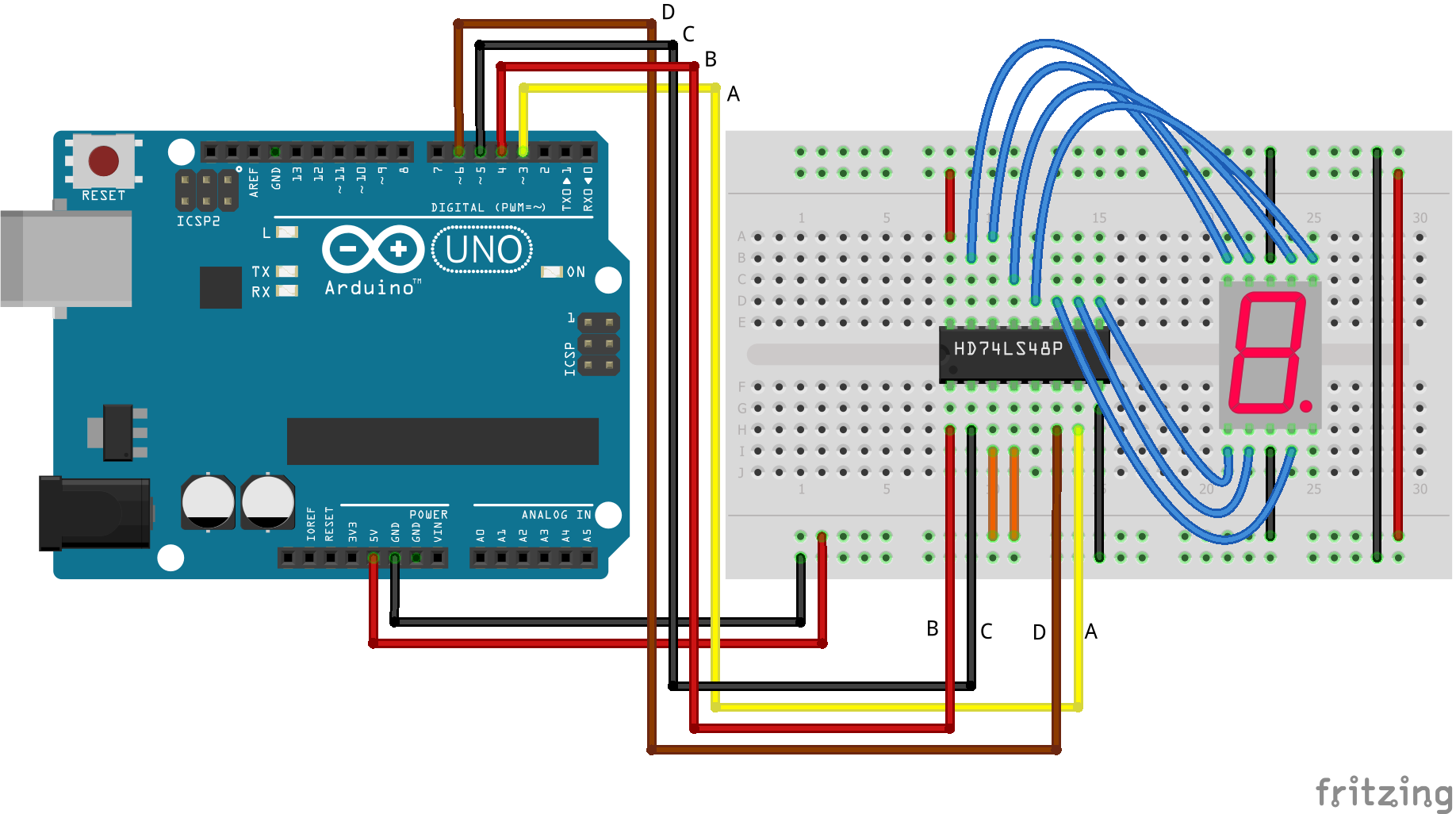
The assembly code would be like this:
start:
RCALL UIAM
UIAM:
LDI R16, 0xFF
OUT DDRD, R16 ; Set PORTD as output
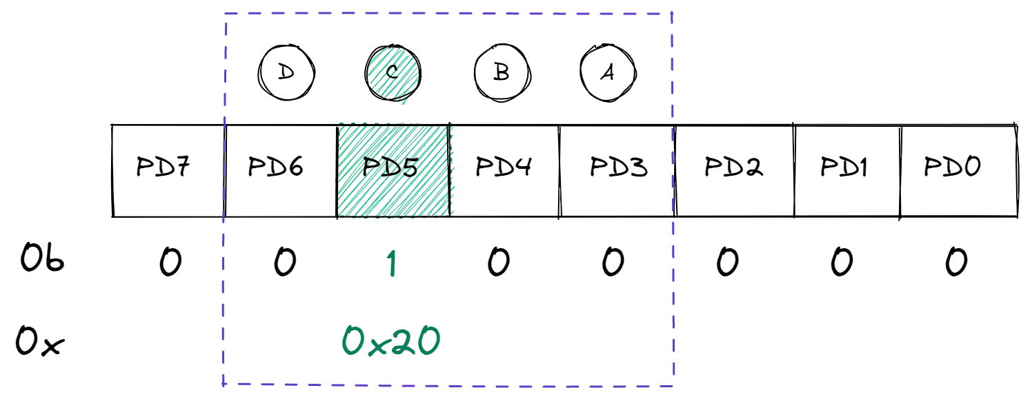
LDI R18, 0X20
OUT PORTD, R18 ; Pin 5 HIGH
RJMP UIAM
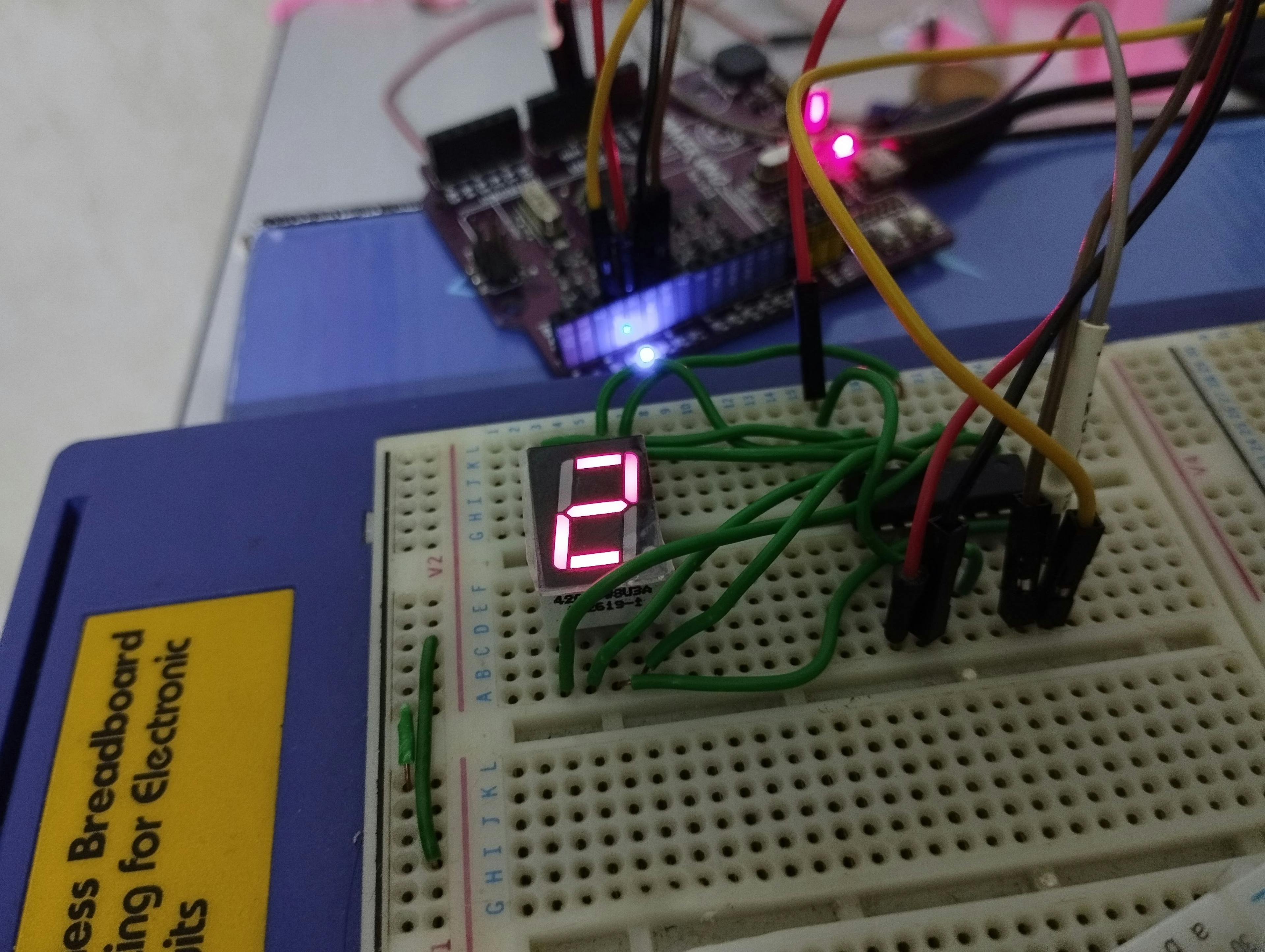
With all of that, it should be displaying digit 4 now:
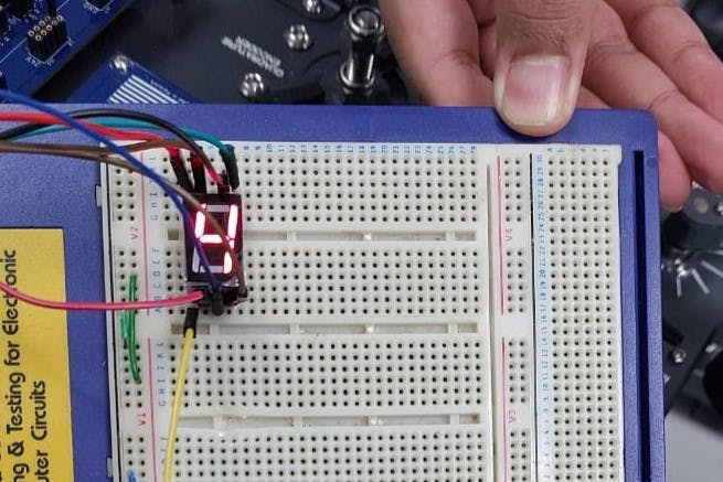
Maybe you were wondering, why 0x20? 0x20 is equivalent to 0010 0000 in binary, representing which PD𝑥 in PORT𝑥 to be set as HIGH. In this case, it's pin 5 (counting from 0).
Ok, enough introductions, now back to our objective, which counts from 0 to 9 and displays on the 7-Segment display.
Back to business
I have already gone through the struggle to make this work, so I'm just going to share the code with you, and explain it along the way.
start:
; initial counter value
ldi r18, 0;
; set PORTD to OUTPUT
ldi r16, 0xff
out ddrd, r16
rcall main
main:
; Output value to GPIO
mov r20, r18 ; Copy content r18 to r20 (temporary)
; Shift bits (according to location of the pins)
lsl r20
lsl r20
lsl r20
out portd, r20
rcall delay
ldi r17, 1 ; increment
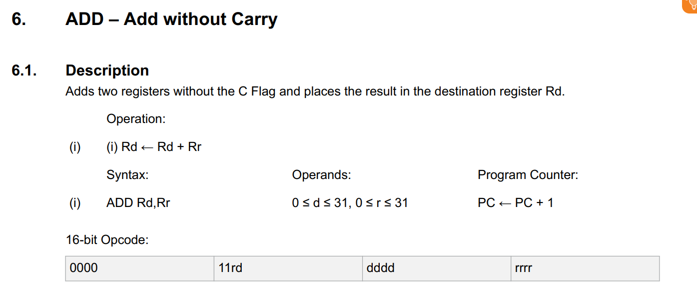
add r18, r17 ; increment current counter
cpi r18, 10 ; compare current counter if match 10
breq reset ; if true, go to reset
rjmp main ; if false, continue looping the 'main' block
reset:
ldi r18, 0 ; reset counter to 0
rjmp main
delay:
ldi r24, 100
ldi r25, 63
ldi r26, 10
L1: dec r26
brne L1
dec r25
brne L1
dec r24
brne L1
nop
ret
Explanation
Let's begin with the start subroutine. It's the first subroutine that will be executed when the program starts. We set the initial value of the counter to 0, and set the PORTD as output.
start:
	ldi r18, 0;

	ldi r16, 0xff
	out ddrd, r16

	rcall main
Then, we jump to the main subroutine by using the rcall instruction.
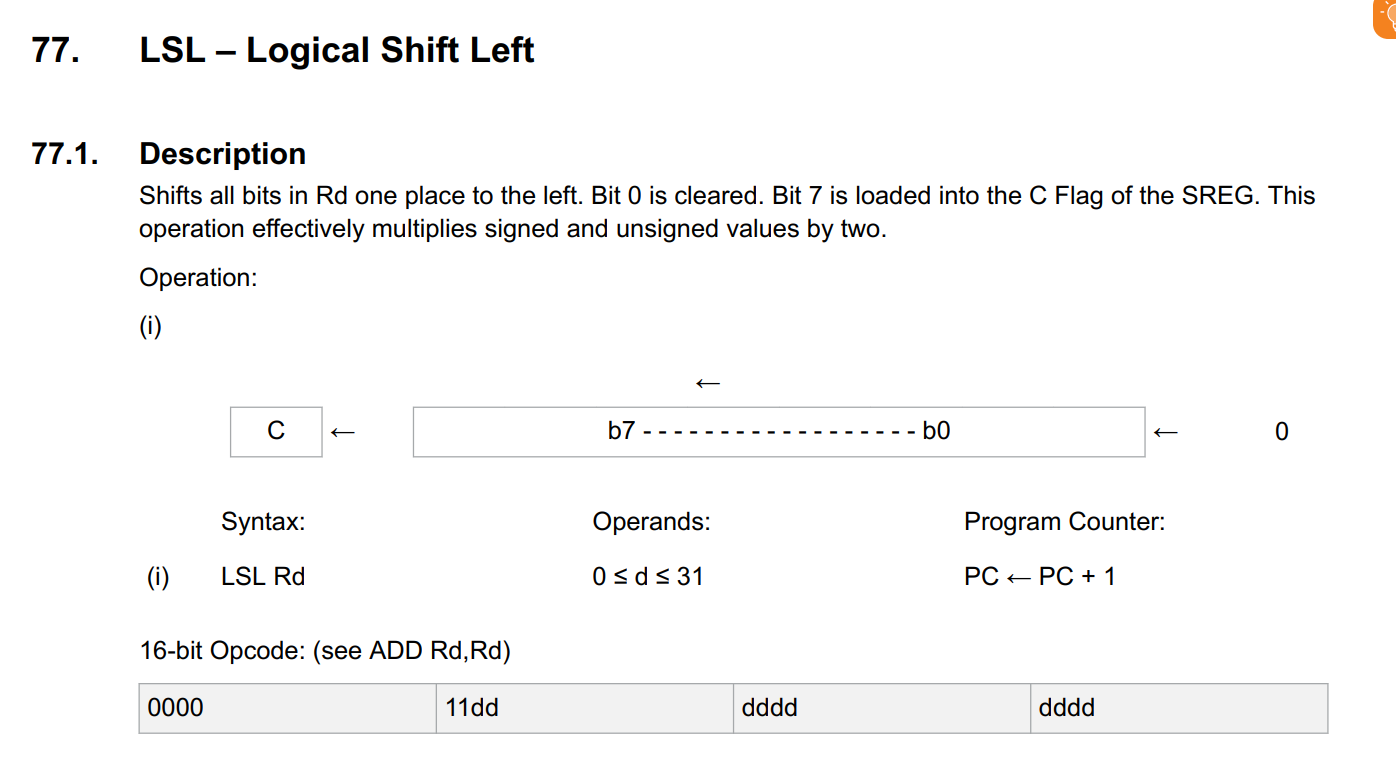
Next, we copy the current counter value to register r20. Same like the example with digit 4 above, we want to map the counter value bits one-to-one with the PORTs. Since our port doesn't start from 0, the bits need be shifted. This can be done through the lsl instruction.
In case it wasn't clear, take a look at the diagram below. So, three lsl instructions there is equivalent with the pins that are empty.
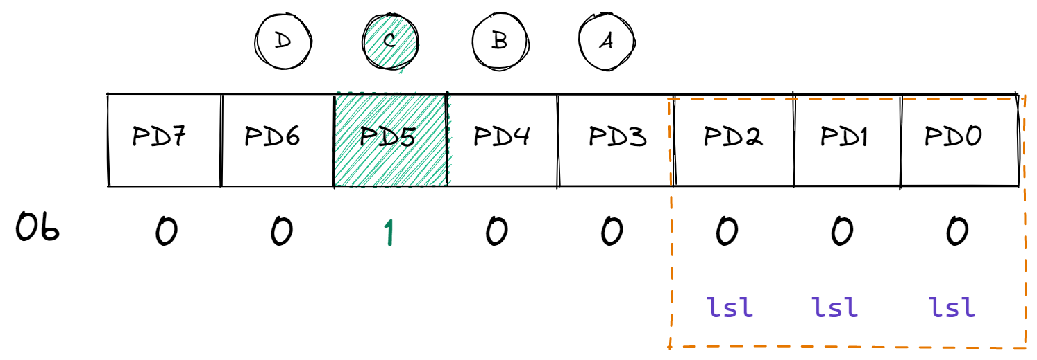
	mov r20, r18

	lsl r20
	lsl r20
	lsl r20
	out portd, r20
Tips
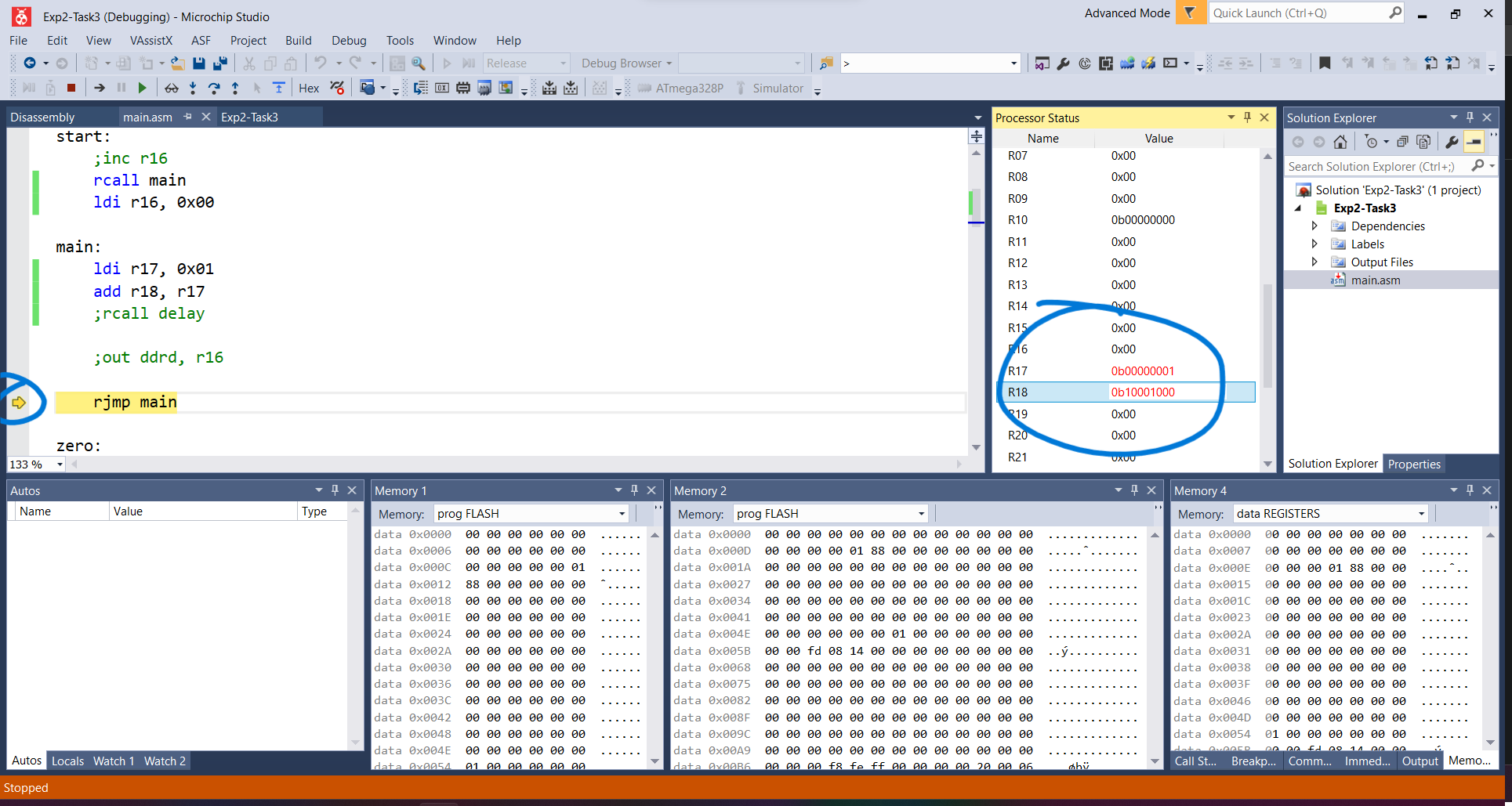
On Atmel Studio, you can set breakpoints etc to easily debug your program. The status register on the left panel is very useful to see the current register value. It's like a Serial.println for us.
Delay is necessary, or otherwise the program ran too fast, and we could not see the clear output
rcall delay
Then, we load the increment value to the register r17. In the next line, using the add instruction, we add the increment value to the current counter value. The addition result is stored in r18 register.
    ldi r17, 1
    add r18, r17
Next, we do not want our counter to count indefinitely, so we need to reset it to 0 when it reaches 9+1. We can do this by using the cpi instruction. The next line, we used the breq (Branch if Equal) instruction to jump to the reset subroutine, otherwise, just loop from the beginning of main.
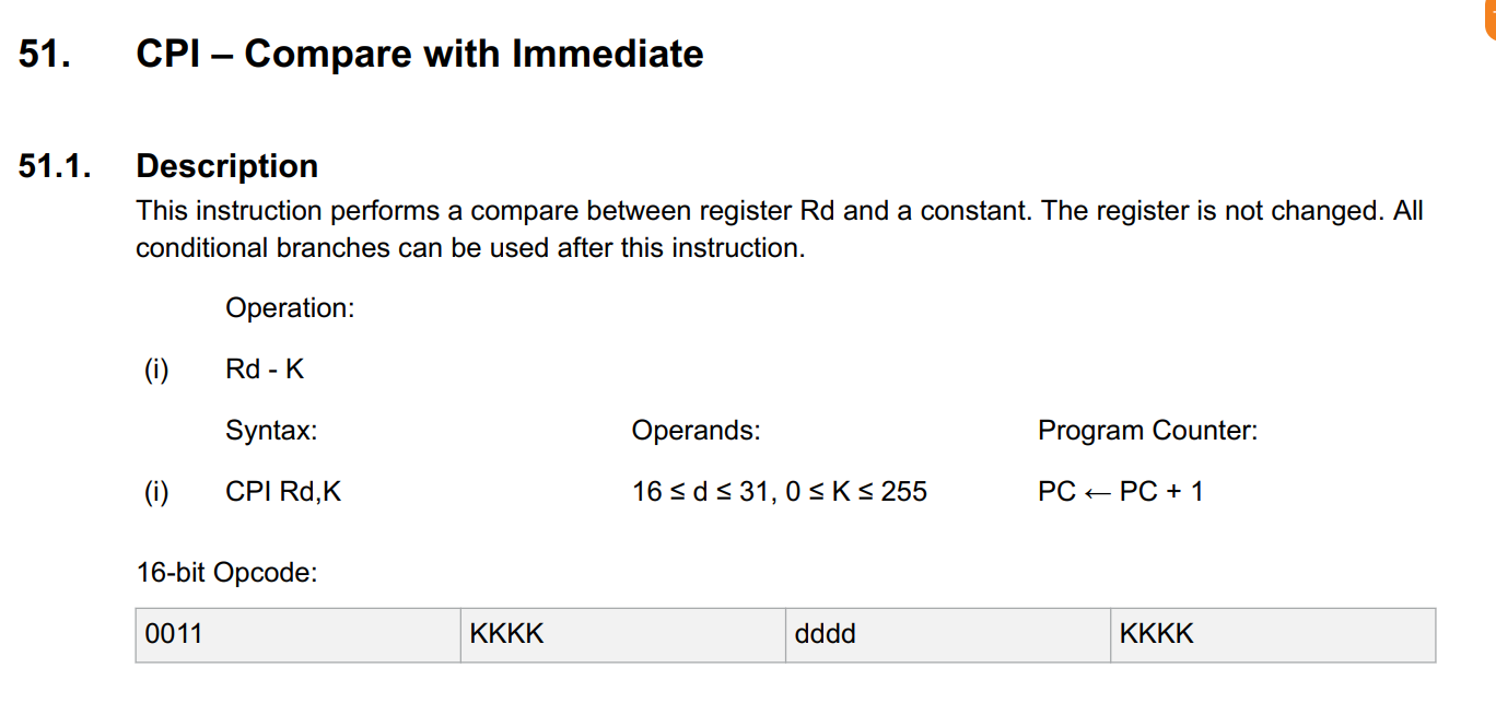
    cpi r18, 10
	breq reset
	rjmp main
In reset subroutine, we just reset the counter value to 0 and jump back to the main subroutine.
reset:
    ldi r18, 0
    rjmp main
That's all. I'm not going to explain about the delay and L1 subroutines. But just keep in mind there are meant to be together, the delay depends on L1 (or vice versa, I'm not sure). Let's see how the results.
Result
Closing remarks
I enjoy making this work using Assembly. I hope you've learned something from this article. Kindly visit here for more Arduino - Assembly examples.
Believe it or not; this code was my first attempt to complete this task as I don't have any idea how to do counter. I know, it is an awful code to look at it, consisting of 100+ LOC, but technically works 😆
Thank you for reading, for any thoughts or suggestions, please leave a comment below. I'll leave you with this meme from r/ProgrammerHumor.